Next: Forward/backward annotation between Lepton and PADS PowerPCB, Previous: BOM netlister backend, Up: Netlister [Contents][Index]
6.3 Lepton RF Cascade Symbols and Netlister
by: Dan McMahill
This document is released under GFDL
December 3rd, 2003
- Overview
- Requirements
- Creating Schematics
- Extracting the Cascade Input File
- Running Cascade
- Appendix A – Symbols in the Library
- Example
- Document Revision History
6.3.1 Overview
This document describes the symbol library and lepton-netlist backend
which support driving RF Cascade
(http://rfcascade.sourceforge.net) simulations from the Lepton
system. Cascade is a noise figure and distortion analysis tool geared
towards radio receiver design.
The basic steps involved with using Lepton as the frontend for Cascade simulations are:
- Create schematics of the circuit.
- Extract the netlist.
- Run Cascade.
6.3.2 Requirements
You will need the following programs to be installed:
- lepton-eda A version of Lepton package.
- RF Cascade
The executable is usually called
cascade. If you do not have Cascade available on your system, you will need to get a copy from http://rfcascade.sourceforge.net.
6.3.3 Creating Schematics
When creating a block diagram in the lepton-schematic editor, use only the
symbols from the cascade library. Every block diagram must have a
‘cascadesource’ element. In addition, the block diagram must be a
simple cascade. No parallel paths or branches are allowed.
All instances must have a unique reference designator. For a receiver block diagram, this is often times best achieved by manually entering them. The only restriction on reference designator names is that they contain no spaces. A descriptive name such as ‘RF Filter’ or ‘First Mixer’ is useful as it will show up in the cascade output report.
6.3.4 Extracting the Cascade Input File
To extract the Cascade input file, run:
lepton-netlist -g cascade -o test.cas file1.sch [file2.sch ...]
For the example file contained in this archive, you can run:
lepton-netlist -g cascade -o example.cas example.sch
The netlist will be left in example.cas.
6.3.5 Running Cascade
Cascade is exceptionally simple to run. Just run:
cascade example.cas > example.out
to run the analysis on the system contained in the file example.cas and write the results to the file example.out. Refer to the Cascade documentation for complete details.
6.3.6 Appendix A – Symbols in the Library
Please note that all instances must have the ‘refdes=’ attribute set.
6.3.6.1 Sources (cascade-source)
Source.
Attributes:
- C=Carrier level in dBm. Optional.
- CN0=Carrier to Noise Spectral Density Ratio in dBm/Hz. Optional.
- CN=Carrier to Noise Ratio in dB. Optional.
- BW=Signal Bandwidth in Hz. Optional, but requred if CN= is used.
6.3.6.2 Defaults (cascade-default)
This symbol sets the default impedance levels as well as the correlation coeffcient used for third order distortion calculations. There are two versions of this symbol. One is used to set the defaults at the beginnng of the definition. The other can be placed in series with the cascade to change the defaults part way through. This is useful if you wish to change impedance levels in the middle of the receiver chain. Attributes:
- RIN=Default block input resistance in Ohms. Optional.
- ROUT=Default block output resistance in Ohms. Optional.
- RHO=Default third order distortion correlation coeffcient. Optional.
6.3.6.3 Elements
Cascade characterizes each block in a system by its gain and optionally noise figure and third order intercept point. As such, there is no distinction between various elements such as amplifiers, filters, and mixers. The Lepton RF Cascade symbol library contains different symbols for clarity in the diagram only. The currently available element symbols are:
Attributes:
Table 1: Element Types
cascade-ampAmplifier
cascade-filterFilter
cascade-mixerMixer
cascade-transformerTransformer
- Gain is specified by one of the following:
-
G=Power gain in dB. -
GP=Power gain in dB. -
GV=Voltage gain in dB.
-
-
NF=Noise Figure in dB. Optional. -
IIP3=Input Third Order Intercept Point in dBm. Optional. -
RIN=Block input resistance in Ohms. Optional. -
ROUT=Block output resistance in Ohms. Optional. -
RHO=Third order distortion correlation coeffcient. Optional.
6.3.7 Example
This appendix provides a simple example of the entire process of generating a schematic, producing a Cascade input file, running an analysis and looking at the result.
6.3.7.1 Example Schematics
Figure 6.1 shows the schematic of a simple receiver signal chain.
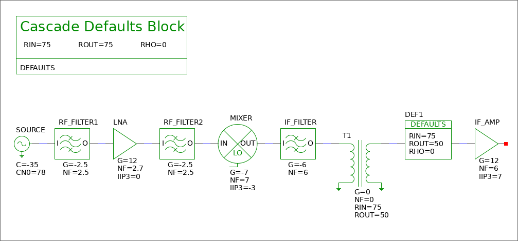
Figure 6.1: Simple receiver signal chain block diagram
Figure 6.2 shows the contents of the example.cas file.
# Cascade (http://rfcascade.sourceforge.net)
# Created with Lepton EDA netlister

# Initial global defaults
defaults RIN=75 ROUT=75 RHO=0

# Source definition
source C=-35 CN0=78 CN=0 BW=1

# Cascaded system
RF_FILTER1 G=-2.5 NF=2.5
LNA G=12 NF=2.7 IIP3=0
RF_FILTER2 G=-2.5 NF=2.5
MIXER G=-7 NF=7 IIP3=-3
IF_FILTER G=-6 NF=6
T1 G=0 NF=0 RIN=75 ROUT=50
defaults  RIN=75 ROUT=50 RHO=0
IF_AMP G=12 NF=6 IIP3=7

# End of netlist created by Lepton EDA netlister
Figure 6.2: Example RF Cascade input file, example.cas
6.3.7.2 Netlist the Design
To netlist the design, run:
lepton-netlist -g cascade example.cas example.sch
6.3.7.3 Run the Analysis
Run the analysis with:
cascade example.cas
6.3.8 Document Revision History
December 3rd, 2003Created cascade.tex